Tips to Simplify Your Data Center Management

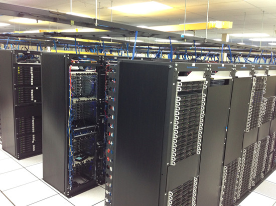
Data center houses a network’s most critical systems and is vital to the continuity of daily operations. Many of us have seen what it looks like. As we all know, the more complex a data center is, the more difficult it can be to ensure efficiency and orderly management—not only of the systems and equipment, but of the working staff as well. How to simplify data center management? This post may give you the answer.

data-center

When several different types of product, tools and resources are used to support a network, complication cannot be avoided. With the rapid development of society, many business demands require the data center to operate quickly and effectively. In order to achieve this goal, various mix-and-match occur, which lead to a complicated data center. Here are several tips to simplify data center management and make it work efficiently.

Emphasize Standardization

With the fast advancement of communications, equipment used in data centers is replaced frequently. Therefore, product standardization is something to keep in mind when upgrading and replacing the equipment, as well as the infrastructure that supports it. By utilizing standardized data center hardware, maintenance can be finished smoother and faster with common approaches, which save time, resources and money.

Choosing Easy Installation and Space-saving Components

A complicated data center environment makes it difficult to identify the root cause of errors or misconfigurations. So selecting some easy installation and space-saving products means shorter installation times, less training time for staff and lower maintenance costs. There are many examples of products that make installation and maintenance simpler for data centers. Here are some examples.

Designed to deliver maximum connectivity performance in a minimal footprint according to standards, LC uniboot patch cable uses a single, unified jacket for both fibers. With this unique structure, it allows up to 68% space-saving in cabling volume, offering easier maintenance and operability. Besides, LC fiber optic connectors can offer higher density and performance in most environments, which makes it popular in many applications.

push-pull-tab-patch-cable

High Density Push-pull Tab Fiber Optic Patch Cable

Push-pull tab patch cable has a special “pull” tab design that enables the connector to be disengaged easily from densely loaded panels without the need for special tools, allowing users easy accessibility in tight areas when deploying in data center applications. With this unique design, high-density fiber cables, such as MPO/MTP fiber cables, offer high density connections between network equipment in telecommunication rooms and data centers. They can be easily installed or removed with one hand, which improve efficiency greatly.

High Density Fiber Enclosure

Fiber enclosure is designed to house, organize and manage fiber connections, terminations, and patching in all applications, providing the highest fiber densities and port counts in the industry contributing to better rack space utilization and minimizing floor space. Loaded with different numbers of FAPs, HD fiber enclosures offer a high-density flexibility for cabling installations of data centers to maximize rack space utilization and minimize floor space.

4u-fiber-enclosure

Of course, except for the cables and enclosures mentioned above, other small components in data centers also cannot be ignored. For instance, cable ties and labels also play a critical role in cabling installations of data centers. In a word, every detail should be taken into consideration when managing a data center.

Preparing for Future-proof Cabling

As we have mentioned above, under this rapid development environment, data centers should be equipped to handle current needs while offering a clear path for future technology requirements. Complex data centers can be simplified when components are deployed that allow you to grow and migrate to new systems in the future without compromising performance or reliability. For example, solutions that offer support for both traditional ST and SC and modern LC and MPO applications support cost-effective, simpler migration to 40G and 100G applications with only a simple cassette or adapter frame change.

Summary

When data center processes and components are simplified, installation and maintenance become easier and less costly, staff resources are freed up for more strategic tasks, troubleshooting becomes less cumbersome and migration is also more easily achieved. All components mentioned above are available in FS.COM. Welcome to visit our website for more detailed information.

Sources:http://www.fiber-optic-components.com/tips-to-simplify-your-data-center-management.html

Things to Know About Laser Optimized Fibers

As transmission speeds over fiber optic networks increase continually, demands for fast speed from 1Gps to 10Gbps, 40Gbps even 100Gbps are also growing day by day. In order to satisfy this demand, a relative term, “laser optimized fiber”, has come into being. However, what is laser optimized fiber? How much do you know about it? Getting to know the answers from this article will help you make preparations for the latest wave in optical communications.

What Is Laser Optimized Fiber?

Laser optimized fiber, usually refers to OM3 and OM4 multimode fibers, is different from standard multimode fiber optic cables such as OM1 and OM2 by incorporating graded refractive index profile fiber optic cable into each assembly. It means, in laser optimized fiber, refractive index of the core glass decreases toward the outer cladding, allowing paths of light towards the outer edge of the fiber to travel more quickly. This increase in speed equalizes the travel time for both short and long light paths, which ensure the accurate information transmission and receipt over much longer distances.

10g-om3-patch-cable

Laser optimized fiber optic cables are used in high speed fiber optic communications. For instance, 10G OM3 fiber optic patch cable is one of typical laser optimized fibers. It is more and more popular in backbone of the WANs (wide area networks) and data processing centers, for it not only optimizes the fiber transmission channel and space usage, but also simplifies the deployment and system test, as well as provides good performance for density installations.

Why Optical Fibers Are “Optimized”?

As we all know, traditional optical systems utilize inexpensive LED (light emitting diodes) light sources. This kind of light source is suitable for lower speeds but not for higher speeds. As the demand for higher bandwidth increased, LEDs no longer keep pace. They could not support greater transmission rates required. Therefore, a high-speed laser light source named VCSEL (vertical cavity surface-emitting laser) appears. Compared with the traditional one, this light source is well suited for 850nm multimode transmission systems, allowing for higher data rates. With the advent of VCSELs, multimode fiber had to be “optimized” for operations with lasers.

laser-optimized-cable

Benefits of Laser Optimized Fiber Cable

Laser optimized multimode fibers offer a unique solution for premise networking applications by enabling data transmission over longer distances, previously only available through single-mode solutions. After VCSELs appear, in order to fully capitalize on the benefits that VCSELs offer, laser optimized cables have been specifically designed, fabricated, and tested for efficient and reliable use with VCSELs. Here are some major benefits of laser optimized fiber cables.

  • Laser optimized fibers have lower total cost. It reduces immediate capital costs by extending the reach of low-cost optical transceivers, reducing or eliminating the need for higher-cost, single-mode fiber.
  • Laser optimized fibers often use multimode optical transceivers which require less power than single-mode transceivers. Besides, it also offers a superior upgrade path to faster applications without the need to replace cabling infrastructure or reconfigure data center architecture.
  • Laser optimized fiber cables have faster speed over longer distances. It allows 100 gigabit Ethernet at distances of up to 600 feet, which provide a more cost-effective solution for data centers when compared with higher cost single-mode optic fiber.
  • Laser optimized fiber is completely compatible with LEDs and other fiber optic applications. They can be installed at slower data rates or higher data rate. The cabling infrastructures based on laser optimized fibers are fully compatible with emerging, current, and older applications, and provides the longest reach possible over multimode fiber.
Summary

Laser optimized fiber optic cable enables data transmission over longer distances previously only feasible with single-mode fiber. It has more advantages when compared with common fiber optic cables. FS.COM supplies various kinds of OM3 and OM4 laser optimized cables as well as other types of optical cables such as OM1, OM2 to meet different cabling requirements. Welcome to visit FS.COM for more detailed information.

Sources:http://www.chinacablesbuy.com/things-to-know-about-laser-optimized-fibers.html

Effective Solutions for 10G/40G Connectivity

As the growing demand for faster access to larger volumes of data, coupled with emerging high-speed network standards and rapidly advancing technology, fiber optic cables and cabling components have become a very popular element in data centers and high-speed networks. And when 10G fiber is the norm in most data centers today, the 40G fiber is also becoming commonplace. In this article, three effective solutions for 10G/40G connectivity will be introduced.

Breakout Cabling Solutions

A breakout cable is a multi-strand cable which is divided into different specification cables. For example, a 40Gb breakout cable has four 10Gb duplex cables totaling eight strands, while a 100Gb breakout cable has 10 duplex cables and 20 strands.

How Does Breakout Cable Work?

To understand how breakout cabling solutions work, take integrating 10Gb servers into a 40Gb network for example. For each port on the switch, an MTP/MPO breakout cable which has an MPO/MTP connector on one end and four duplex LC connectors on the other end is needed. The MPO/MTP connector is plugged into the transceiver that connects with 40Gb switch and each duplex LC connector plugs into a 10Gb port on each server. If the switch has up to 32 40G ports, up to 128 10G devices can be connected to it using breakout cables.

breakout-cabling-solution

Advantages

This breakout cabling solution enables slower equipment to be connected to higher-speed equipment successfully, such as the 10Gb servers and 40Gb switch in our example. Up to 128 10Gb devices can be connected to a 32-port 40Gb switch.

MTP Modular Cassettes Solutions

MTP cassette modules provide secure transition between MTP and LC or SC discrete connectors. They are used to interconnect MTP backbones with LC or SC patching. Supporting various network cabling standards, the cassettes are easy to mix, match, add and replace as the connectivity needs grow or change.

How Does MTP Modular Cassette Work?

Modular fiber cassettes are the key to modular systems. Available in multiple variations, the cassettes allow users to interconnect different fiber speeds simply by plugging standard LC cables into one side of the cassette and one or more standard MPO/MTP cables into the other side.

modular-patch-panel-solution

For 10G connectivity, MTP/MPO cassettes are used to connect 10G device to 10G device, especially when the distance between two devices is too long. And for 40G connectivity, MPO/MTP cassette is used to connect 10G device to 40G device. Modular patch panel solutions offer users an easy-to-use solution that works with the equipment of today and can easily be transitioned for the networks of tomorrow.

Advantages

Modular cassette solution also has many advantages. First, this solution offers flexibility and scalability for network upgrade. Second, with fiber modular cassettes, this solution allows users to manage cables in any direction—horizontal or vertical, front or back. Finally, by managing varying port densities and speeds in a single high-density patch panel, users can save valuable rack space and data center costs.

Fiber Breakout Panels Solutions

Fiber breakout panels are ready for plug-and-play deployment out of the box. They provide increased access between ports, thus enabling the ease of moves, adds, and changes of cables. It’s the increased access that help fiber breakout panels offer a cost saving, simple and efficient cable management solution for future high-speed network connection.

How Does Breakout Panels Work?

Fiber breakout panels offer a simple, cost-effective alternative to breakout cables. To understanding how it works, let’s take one of 40G QSFP+ breakout patch panel for example. The 96 fibers MTP-LC 1U Ultra Density 40G QSFP+ breakout patch panel has 48 duplex LC ports front and 12 MTP Elite rear ports. When it’s installed, the 40GE QSFP ports with MTP fiber cable will be connected to the back of the panel, and then LC fiber cables will be linked to the LC port. This 40GB QSFP breakout panel logically groups the ports in 4 duplex LC ports, and is available for single-mode or multimode applications.

multimode-singlemode-fiber-breakout-panel

Advantages

Breakout panels solution can connect different equipment such as 10G, 40G and 100G, offering more flexibilities for network cabling. Besides, as the breakout panels are pre-terminated, they can be easily installed and help save installation time.

Conclusion

With increasingly higher network speeds always just around the corner, network build and upgrade also get much attention. Choosing suitable connectivity solution for 10G/40G connectivity which allows you to meet your current connectivity needs while simultaneously investing in your future also should be attached more importance. The contents above give an explanation of three cabling solutions. Hope it may help you.

Sources:http://www.fiber-optic-components.com/effective-solutions-for-10g-40g-connectivity.html

Things You Need to Know About Patch Panel

Nowadays how to achieve efficient cable management is an essential aspect in network cable installation. Patch panel, as a crucial element of an interconnected network cabling, is able to realize the connection, allocation and scheduling of cable links easily. This post will introduce some information about patch panels which can help you get further understanding of them.

What Is a Patch Panel and How Does It Work?

Patch panels, also called jack fields and patch bays, are network parts held together within telecommunication closets that connect incoming and outgoing local area network (LAN) lines or other communication, electronic and electrical systems. If engineers want to set up a wired network which contains multiple wall ports in various rooms, patch panels can offer a simple, neat and easy-to-manage solution. There are various patch panels based on the number of ports like 12 Ports, 24 Ports, 48 Ports, etc.

patch-panels-group

When patch panels are deployed in network systems, its major function is to bundle multiple network ports together to connect incoming and outgoing lines. For example, when patch panels become part of a LAN (local area network), they can link computers to outside lines. And those lines, in return, allow LANs to connect to wide area networks or other Internet. With patch panels, engineers just need to plug and unplug the corresponding patch cords to arrange circuits, which improve efficiency greatly.

The Importance of Patch Panels

As we all know, patch panels are typically attached to the network racks, mostly above or below the network switches. They consist of ports to quickly connect cables. Available in different sizes and configurations, patch panels can be customized to fit different network requirements. But all patch panels have a similar feature that they are important for networks to configure new equipment or phase out old components.

Patch panels from main links are to collect data and route it to where its destination. They are so critical to a system that if anything goes wrong with them, the entire system may fail. That means that patch panels are very important to network system.

Further more, although there are no physical limits existing for a patch panels’ size, many of them have ports from 24 to 96. And for a larger network, hundreds of ports may be needed, which is another important factor—as the network grows, more ports mean the ability to accommodate ever-expanding demand.

Besides, patch panels also help electricians and network engineers by offering convenient, flexible routing options. Because a patch panel has numerous ports in close proximity, cables can be routed, labeled and monitored easily and efficiently.

Copper or Fiber Patch Panel?

There is no doubt that patch panels are extremely important in cabling systems. And they are one of the few components used in both copper and fiber cabling networks.

copper-patch-panel-vs.-fiber-patch-panel

Copper patch panels are typically made with 8-pin modular ports on one side and 110-insulation displacement connector blocks on the other side. Wires coming into the panel are terminated the insulation displacement connector. On the opposite side, the 8-pin modular connector plugs into the port which corresponds to the terminated wires. With the copper panel, each pair of wires has an independent port. And fiber patch panels need two ports for a pair of wires, one for the transmitting end and another for the receiving end. Fiber panels tend to be faster to operate than copper ones. Of course, they are also more expensive.

Therefore, when it comes to copper patch panel, each pair of wires has a port. While fiber patch panel requires two ports, but it is easier to be installed. What’s more, some professionals think there is no real difference in the performance and construction, while others have different opinions. They maintain that the fiber patch panels are better, even though they are more expensive than the copper counterpart. However, no matter what type of patch panels you choose, they must be based on practical situations.

Summary

As the growing demands for more effective cabling, patch panels also get more development. Manufactures are now trying to produce more convenient patch panels such as front-access panels, which allow users to terminate and manage cables from the front. Getting further understanding of patch panels can help you choose suitable patch panels for your networks.

Sources:http://www.chinacablesbuy.com/things-you-need-to-know-about-patch-panel.html

Guide to Choose Category 6A Cable for 10G Network

With the growing demand for high bandwidth and network systems venturing into new areas such as factory environments, the need for copper cables is also on the rise. Category 6A cable, as a new infrastructure performance, has been widely accepted in 10G networks. Then how to select the one that will provide the characteristics needed? This article may help you get the answer.

Overview of Category 6A Cable

Category 6A, also refer to Cat 6A, is a standardized twisted pair cable designed for Ethernet and other network system. Compared with Cat 5e and Cat 6, Cat 6A can double data transmission bandwidth from 250 to 500 MHz, reduce the chance of crosstalk interference, and offer superior reliability and transmission speeds through longer length of cable. For example, Cat 6A supports 10gBASE-T to 100 meters in channel length, which makes sure that it can be deployed in the fastest Ethernet applications. Different from Cat 6 cables, Cat 6A cables are often shielded, making them ideal for industrial applications where additional interference may be a concern.

cat-6a-cable

Considerations When Choosing a Cat 6A Cable

There are various kinds of Cat 6A cables in the market such as round shielded and flat shielded. And many factors may affect the performances of Cat 6A in network systems. Here are the important considerations to weigh when choosing a Cat 6A cable.

UTP or F/UTP?

There are two types of Cat 6A cable: unshielded (UTP) and shielded (F/UTP). UTP cable is the common unshielded cable. While the F/UTP means the cable consists of 4 unshielded twisted pairs. However, it contains an outer foil shield. Due to the use of fillers as a barrier against alien crosstalk, UTP cables tend to be larger in diameter than shielded cables, which means they need more investments to support the extra conduit and hanging devices. Generally, Cat 6A seems to be a better choice for 10G networks. But they are vulnerable to installation abuse as the position of the pairs inside the cable may be changed, affecting the proximity of the pairs and their position relative to the overall foil shield, thus changing the transmission properties of the pairs. So it’s important to choose the suitable one based on your practical applications.

cat-6a-utp-cat-6a-futp1

Cable Size and Weight

Due to the higher operating frequencies of Cat 6A, Cat 6A cables are larger than Cat 6 cables. Large size means fewer cables can fit into a cable tray or conduit, which is a problem that must be considered when selecting Cat 6A cables.

Installation Complexity

As we all know, because the Cat 6A cables have more twists in copper pairs and thicker outer jacket, most of them are larger than common cables. Therefore, more time is needed to install and terminate those cables. Making a proper plan to do Cat 6A cabling is necessary according to the project process.

Channel Length

When delivering PoE, some small-diameter Cat 6A cables may not support the full 100m distance per-channel. However, there is no doubt that Cat 6A cable can support full 100m distance in other data transmission. A cable that can handle the full 100 meters not only provides an extra margin of performance, but supports a wider range of data center configurations including top-of-rack, end-of-row and middle-of-row configurations. So you can decide whether to deploy Cat 6A cables according to your requirements.

Bend Radius

A cable that has larger cable diameters also comes a larger bend radius, which is important when routing cables in tight spaces such as inside wall cavities. The bend radius also has an impact on the ability to route cables for maximum airflow within racks. The smaller the bend radius, the easier the cable is to route and install.

Summary

CAT6A is currently a good choice for 10GbE networks. It’s essential to evaluate the current and future throughput needs before selecting the appropriate Cat 6A cables. It’s known to all that cable infrastructure is complicated and costly to replace if upgrading is necessary. Hence, before choosing a Cat 6A cable, all factors should be taken into consideration so that your installed systems can get optimization!

Sources:http://www.fiber-optic-components.com/guide-choose-category-6a-cable-10g-network.html

Considerations for Choosing the Right Network Rack or Cabinet

When designing a data center, server room or network closet, deciding which racks or cabinet to deploy and how to configure them should be the most important thing to be considered. Because a right network rack or cabinet can bring a lot of benefits such as improving power protection, cooling, security as well as cable management. This post will list several considerations that need to be paid attention to when buying a network rack or cabinet.

Basics of Network Rack or Cabinet

Network rack or cabinet is essential frame structures designed for housing standard 19” rack-mount equipment-servers, routers, switches, audio or video gear, etc. It allows for better organization and offers additional security and cable management. Network racks or cabinets are mainly used in data centers, server rooms, audio or video installations, some also deployed in industrial environments such as a factory floor. Usually, there are three common types of network racks.

network-racks

  • Rack enclosure—rack enclosures have removable front and rear doors, removable side panels and four adjustable vertical mounting rails. They are ideal for applications that require heavier equipment.
  • Open-frame racks—open frames have no sides or doors, but with mounting rails. They are good for applications where the racks do not need to control airflow or provide physical security.
  • Wall-mount racks—these racks are often attached to the wall, which helps save space and fit in areas where other racks can’t. They also can be enclosed cabinets or open frame racks.
Considerations When Choosing a Network Rack or Cabinet

There are various kinds of network racks or cabinets on the market now. If you are in the market and trying to decide on which is best for you, the following references may help you.

img_0755

Physical Dimensions and Weight of Your Equipment

Knowing clearly what you have, then it may be easy to choose what you need. The first factor needs to be considered is the physical dimensions and the weight of your equipment. Some equipment maybe bulky or heavy, and they might only suit in the racks or cabinets that are designed to be placed on the floor. While some equipment might be smaller which can fit inside desktop or wall-mount cabinet. In order to organize your equipment, it’s important to consider the practical situations of your own equipment.

Size and Space

Choosing a network rack or cabinet with enough internal space to house your current equipment and enough room to accommodate planned future expansion is vital for your network systems. Keep in mind that space for accessories such as environmental monitoring devices, sensors, remote power management devices and battery back-up may also be necessary. So the size of a rack or cabinet including height, width, depth and load rating should be taken into consideration.

Access Points to Equipment

Different equipment applications need different access points. Some may need only front access, while others may need side or back access. Decision on what type of access points you might need to manage your equipment and ensure the rack or cabinet you choose can offer you the access point you need.

Cooling System

Some applications like data centers or server rooms require to keep equipment cool without any special measures. Therefore, when choosing racks or cabinets, cooling system is also a factor that needs to be considered. Since the structures of different racks are various, the airflow in them is also different. For example, open frame racks offer very little control over airflow although they are great for some applications. The best racks for managing equipment cooling are floor-standing rack enclosures because they provide the most control over airflow.

Power Distribution

As we all know, equipment in racks also requires many power outlets, especially most IT equipment has more than one cord and power supply. You also need a way to reach distant wall outlets from the rack. Power distribution units can solve this problem. And they also can offer features like current monitoring, remote management, automated alerts and individual outlet control.

Summary

Network racks or cabinets are important in organizing equipment in data centers or server rooms. And the process of choosing a suitable network rack or cabinet is often nothing more than a cost exercise. No matter what rack or cabinet you choose, the suitable is better. In a word, choosing the right racks or cabinet and configuring them properly will ensure your equipment work reliably and effectively.

Sources:http://www.chinacablesbuy.com/considerations-choosing-right-network-rack-cabinet.html

Optical Switches Overview

An optical switch is a device that can selectively switch light signals that run through in optical fibers or integrated optical circuits from one circuit to another. That is to say, optical switches can transfer light signals between different channels in communication networks. As the growing popularity of Internet and telephone, greater quantities of data managed by communication networks also expanded. Optical switching technology provides a perfect solution to fully exploit capacity of optical systems. The main focus of this post is to introduce basics of optical switches in optical communication.

optical-switches

Working Principles & Functions of Optical Switches

As we all know, when a light signal runs through from one computer to another in fiber optic networks, it may be required to move the signal between different fiber paths. To accomplish this, a switch is required to transfer the signal with a minimum loss. Optical switch is a technology needed. The optical switch we often see is operated by mechanical method which just moves fiber or other bulk optic components. But they can offer unprecedented high stability and unmatched low cost performance.

Optical switches are mainly deployed in establishing the light path. They feature scalability and highly reliable switching capacity. Following are the major functions that optical switches bear in optical cross networks.

  • Protection. Sometimes a failure of some single point can cause the whole network breaking down. And the protection switching is to protect the transmission data, which can avoid network fault before finding the failure causes.
  • Optical add/drop multiplexing. Optical switches must be equipped with the capability that can add or delete the wave channels without any electronic processing. This kind of optical switches is also called wavelength selective switches.
  • Optical spectral monitoring. Optical spectral monitoring is a network management operations. In this process, operators receive a small portion of optically tapped signal for monitoring power level, wavelength accuracy and optical cross talk.
Common Types of Optical Switches

As data requirements grow, the traditional electrical switches no longer meet people’s demand. There are two major types of optical switches on the market: opto-mechanical optical switches and MEMS (Micro-electromechanical Systems) optical switches.

Opto-Mechanical Optical Switches

Opto-mechanical optical switch is an old type of switches but the most widely used one. It can produce different optical path selections out of a plurality of optical path sections that are oriented in different spatial directions. Hence opto-mechanical optical switches can be used in multi-channel optical power monitoring, optical local area networks, switching multiple laser sources or optical receivers in Ethernet networks. They are also very useful in optical fiber, components or systems testing and measurement, as well as applications in multi-point fiber sensor systems. Generally, according to the number of redirecting signals, opto-mechanical optical switches have different configurations such as 1×1, 1×2, 1×4, 1×16, etc. In simple terms, the 1×8 opto-mechanical optical switch module connects optical channels by redirecting an 1 incoming optical signal into a selected signal from 8 output fibers. This kind of optical switches can achieve excellent reliability, insertion loss, and cross talk.

opto-mechanical-optical-switches

MEMS Optical Switches

MEMS optical switches use a micro-mirror to reflect a light beam. And the direction that the light beam is reflected can be changed by adjusting the angle of the mirror, which allows the input light to be connected to any out port. It is a compact optical switch which connects optical channels by redirecting incoming optical signals into the selected output fibers. And the switching state is highly stable against environmental variations of temperature and vibration due to its unique design. In some degree MEMS optical switch can be considered as a subcategory of opto-mechanical switches. But it is distinguished from opto-mechanical switches in many aspects such as the characteristics, performance and reliability. The most obvious is the opto-mechanical switch has more bulk compared to other alternatives, but the MEMS switch overcomes this. Besides, MEMS optical switches also have different configurations such as 1×8, 1×12, 1×16, etc.

1x8-mems-optical-switch

Summary

As the increasing growth of high speed transmission demand for networks, optical networks have become the most cost-effective solution. Optical switches play a vital role in today’s optical network system. They can offer users significant power, space and cost savings. Now different optical switches are available on the market, so you can choose a suitable one based on your requirements.

Sources:http://www.fiber-optic-components.com/optical-switches-overview.html

Guide to Punch Down Tool

Punch down tool, sometimes called krone tool, is a small hand tool that technicians often use to connect telecommunication or network wires to punch down block, patch panels, keystone module and surface mount boxes. It usually comprises a handle, a spring mechanism and a removable slotted blade that can cut off excess wires. Having a dependable punch down tool can help you save time when installing cables, for it allows quick and effective cross-connection of wires. This article aims to introduce how to operate and choose a right punch down tool in cabling projects.

punch-down-tools

Operations of Punch Down Tool

It’s common to cut down or secure wires when technicians are installing cables. In order to ensure the wires are secure, it’s essential to use a punch down tool to trim and contain them in a basic jack. Then how to use a punch down tool? Take punching down a jack for example.

Step one. Strip back the cable jacket. Put the cable into a striping tool and spin it around a few times. Remove the jacket after making sure the jacket is out. Then gently pull away the wire pairs from the center of the wires to make them fan out. Try to strengthen the ends so that you can make them easier to terminate later.

Step two. Put the wires in the jack. Get rid of the protective cover of the jack and put the cable into the block of the jack. Then insert each branch of the wires into its own separate slot, making sure that the wire matches the A or B configuration.

put-the-wire

Step three. Terminate the conductor wires. Press the punch down tool on the conductor wires to cut them. Make sure the cut part of the blade comes into contact with the long sturdy side of the jack, which will ensure the wires to be cut are flush with the jack. In this process, try to punch straight down to prevent the jack from bending. Once you heard a loud click, it means you have terminated the wire correctly.

terminate-the-conductor-wires

Step four. Check out the wires. Having finished the termination, do not forget to inspect it. Try to look at each wire to make sure there is no overhang out the side of the jack. Once ensuring the termination is finished successfully, remember to snap a dust cap in place so that the wires are protected.

Considerations for Choosing a Right Punch Down Tool

If you have experience of terminating cables like Cat5e, Cat6 or Cat6a which are needed to connect with keystone jacks, you may know clearly how important it is to have a suitable punch down tool at your side when installing cables. If you want to make your installation work faster and easier, the following considerations may help you.

Improve speed. In order to finish work faster, the first factor to consider is speed. As we have mentioned above, technicians must first strip the outer jacket and put the wire in the right slots during the punch down process. Therefore, a good punch down tool needs to help technicians finish the procedure quickly.

Increase accuracy. This is another factor technicians need to consider. You can image that if a technician has to terminate more than one hundred wires, how can he ensure that no mistake occurs all the time? Improper termination can result in network downtime and waste technicians’ time and resources. So whether a punch down tool can help workers increase accuracy or not should be taken into consideration.

Reduce fatigue. After working for a long time, tiredness cannot be avoided. Reducing hand fatigue is a critical factor in wire terminations, especially for technicians who will work in large job sites. Because small mistakes may lead to lots of sources wasted.

Usability. Good punch down tools should have features such as easy-to-use handles and easy for operations, which allow for high usability across a wide range of settings and requirements.

Summary

Punch down tools are a necessary part in cable installations. A decent tool can make the work of technicians easier when installing and maintaining cable, and it also can help operators save money. In a word, it’s beneficial to choose a suitable punch down tool.

Sources:http://www.chinacablesbuy.com/guide-punch-tool.html