How to Realize 16 Channels Transmission in DWDM Network?

DWDM MUX/DEMUX plays a critical in WDM network building. 16 channels transmission is very common in DWDM networks. How to realize it in a simple way? This article intends to introduce two solutions to achieve 16 channels with different types of components. Which one is more cost-effective and competitive? The comparison between the them also will be explored. Hope it will help you when choosing fiber mux for your DWDM networks.

wdm network

Solutions to Achieve 16 Channels Transmission in DWDM Network

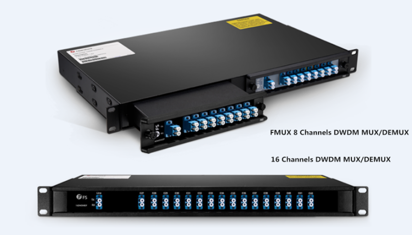
In order to illustrate the solution more clearly, I take two types of DWDM MUX/DEMUX as an example. One is the traditional 16 channels dual fiber DWDM MUX/DEMUX. Another is two FMU 8 channels dual fiber DWDM MUX/DEMUX. The latter has an expansion port.

Solution One: Using Traditional 16 Channels DWDM MUX/DEMUX

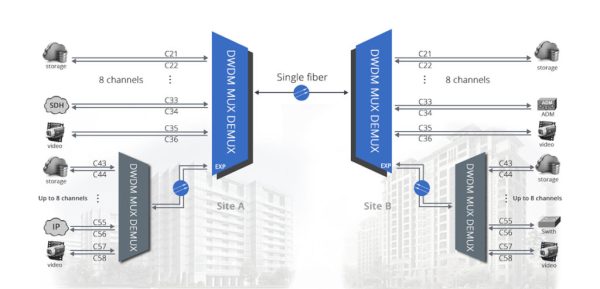
The 16 channel DWDM MUX/DEMUX is a passive optical multiplexer designed for metro access applications. It’s built fiber mux and demux in one unit and can multiplex 16 channels on a fiber pair. In addition, this type of fiber mux also can be added some functional ports like expansion port, monitor port and 1310nm port, which make it possible to increase network capacity easily. The following is a simple graph showing the 16 channels transmission with this traditional DWDM MUX/DEMUX.

16 channels dwdm mux demux

Solution Two: Using Two FMU 8 Channels DWDM MUX/DEMUX Modules

The FMU 8 channels DWDM MUX/DEMUX provide 8 bidirectional channels on a dual strand of fiber. Usually they are used together. Unlike the 16 channels DWDM MUX/DEMUX, this FMU 8 channels one has a more compact size, for it only occupies half space in a 1U rack. Put two FMU 8 channels DWDM MUX/DEMUX modules into one 1U two-slot rack mount chassis. two 8 channels DWDM MUX/DEMUX with different wavelengths are connected through the expansion port to realize 16 channels transmission in a DWDM network. Here is a graph showing how to achieve 16 channels DWDM transmission with these two 8m channels fiber muxes. As shown in the figure, two 8 channels DWDM MUX/DEMUX with different wavelengths are connected through the expansion port to realize 16 channels transmission in a DWDM network.

8 channels

16CH DWDM MUX and Two FMU 8CH DWDM MUX: What’s the Difference When Deployed?

From the content above, we can see both solutions can realize the 16 channels transmission in a DWDM network. Then, are there differences between them? Or which is more competitive? Here is a simple analysis of the two solutions.

fiber mux

Firstly, comparing the two graphs above, the FMU 8 channels DWDM MUX/DEMUX are connected together by an expansion port, that’s why it can deliver 16 channels services like the traditional one. Except for connecting 8 channels DWDM MUX/DEMUX, the FMU fiber mux with expansion port also can be combined with other channels fiber mux like 2 channels, 4 channels or other channels, which offer more flexibility for optical network deployment and upgrade. And you can add DWDM into CWDM networks at some specific wavelengths with FS.COM FMU fiber mux.

Secondly, DWDM MUX/DEMUX price is always an important point that many network operators pay attention to. Therefore, when buying a fiber mux, the cost is a critical point to consider. If you search on Google, you will find the lowest price is $1100 in FS.COM. And the cost of using two 8 channels MUX/DEMUX is the same as the deployment of one 16 channels MUX/DEMUX. However, compared with the 16 channels DWDM MUX/DEMUX, the FMU 8 channels fiber mux provides a competitive solution for small networks which needn’t to buy a full-channel fiber mux that supports all 16 channels or more channels.

Conclusion

From the comparison above, the FMU 8 channels DWDM MUX/DEMUX is more flexible and cost-effective when deployed in WDM networks. How to choose is based on the requirements of your networks. FS.COM supplies two different types of these WDM MUX/DEMUX. Here is a simple datasheet of them. If you have more requirements for additional wavelengths, welcome to visit http://www.fs.com for more detailed information.

Application
ID
Description
16 channels
26569
16 ch. DWDM Mux Demux, C27-C42, , IL <4.6dB, duplex LC/UPC
8 channels
61646
8 ch. Dual Fiber DWDM Mux Demux, C53-C60, with expansion port, IL <4.6dB, LC/UPC

Sources:http://www.fiber-optic-tutorial.com/16-channels-dwdm-mux-demux-in-dwdm-network.html

Understanding WDM MUX/DEMUX Ports and Its Application

Wavelength division multiplexing (WDM) is a commonly used technology in optical communications. It combines multiple wavelengths to transmit signals on a single fiber. To realize this process, CWDM and DWDM mux/demux are the essential part. As we all know, there are several different ports on the WDM mux and demux. This article will give a clear explanation to these ports and their applications in WDM network.

Overview of Different Ports on WDM MUX/DEMUX
Line Port

Line port, sometimes also called as common port, is the one of the must-have ports on CWDM and DWDM Mux/Demux. The outside fibers are connected to the Mux/Demux unit through this port, and they are often marked as Tx and Rx. All the WDM channels are multiplexed and demultiplexed over this port.

Channel Port

Like the line port, channel ports are another must-have ports. They transmit and receive signals on specific WDM wavelengths. CWDM Mux/Demux supports up to 18 channels from 1270nm to 1610nm with a channel space of 20nm. While DWDM Mux/Demux uses wavelengths from 1470nm to 1625nm usually with channel space of 0.8nm (100GHz) or 0.4nm (50GHz). Services or circuits can be added in any order to the Mux/Demux unit.

40ch dwdm mux demux

Monitor Port

Monitor port on CWDM and DWDM Mux/Demux offers a way to test the dB level of the signal without service interruption, which enable users the ability to monitor and troubleshoot networks. If the Mux/Demux is a sing-fiber unit, the monitor port also should be a simplex one, and vice verse.

Expansion Port

Expansion port on WDM Mux/Demux is used to add or expand more wavelengths or channels to the network. By using this port, network managers can increase the network capacity easily by connecting the expansion port with the line port of another Mux/Demux supporting different wavelengths. However, not every WDM Mux/Demux has an expansion port.

dwdm mux demux

1310nm and 1550nm Port

1310nm and 1550nm are one of WDM wavelengths. Many optical transceivers, especially the CWDM and DWDM SFP/SFP+ transceiver, support long runs transmission over these two wavelengths. By connecting with the same wavelength optical transceivers, these two ports can be used to add 1310nm or 1550nm wavelengths into existing WDM networks.

Application Cases of Different Ports on WDM MUX/DEMUX

Although there are several different ports on WDM Mux/Demux, not all of them are used at the same time. Here are some examples of these functioning ports in different connections.

Example One: Using 8 Channels CWDM Mux/Demux with Monitor Port

cwdm mux demux with monitor port

This example is a typical point-to-point network where two switches/routers are connected over CWDM wavelength 1511nm. The CWDM Mux/Demux used has a monitor port and 1310nm port, but the 1310nm does not put into use. In addition, an optical power meter is used to monitor the power on fibers connecting the site A and B.

Example Two: Achieve 500Gbps at Existing Fiber Network with 1310nm Port

dwdm mux with 1310nm port

In this example, two 40 channels DWDM Mux/Demux with monitor port and 1310nm port are used to achieve total 500Gbps services. How to achieve this? First, plug a 1310nm 40G or 100G fiber optical transceiver into the terminal equipment, then use the patch cable to connect it to the existing DWDM network via the 1310nm port on the DWDM Mux/Demux. Since the 1310nm port is combined into a 40 channels DWDM Mux, then this set-up allows the transport of up to 40x10Gbps plus 100Gbpx over one fiber pair, which is total 500Gbps. If use 1550nm port, then the transceiver should be available on the wavelength of 1550nm.

Example Three: Stack Two CWDM MUX/DEMUX Using Expansion Port

cwdm mux with expansion port

The connection in this example is similar to the last one. The difference is that this connection is achieved with expansion port not 1310nm port. On the left side in the cases, a 8 channels CWDM Mux/Demux and a 4 channels CWDM Mux/Demux are stacked via the expansion port on the latter Mux/Demux. And the two 4 channels CWDM Mux/Demux are combined with the line port. If there is a need, more Mux/Demux modules can be added to increase the wavelengths and expand network capacity.

Summary

Different ports on the CWDM and DWDM Mux/Demux have different functions. Knowing more their function is helpful in WDM network deployment. FS.COM supplies various types of CWDM and DWDM Mux/Demux for your preference. And customer services are also available. If you have any needs, welcome to visit our website http://www.fs.com.

Sources:http://www.fiber-optic-components.com/understanding-wdm-muxdemux-ports-application.html

How to Realize Single Fiber Connection in WDM System?

As we all know, fiber optical networking has two transmission ways: dual fiber transmission and single fiber transmission. The difference between them is that the former one requires two fibers—one is for transmitting and the other is for receiving, while the latter only uses one fiber for both transmitting and receiving. Single fiber transmission emergence reduces network deployment cost, especially in WDM systems. This blog intends to introduce how to achieve single fiber connections in CWDM and DWDM networks.

Understanding Single Fiber Transmission

Single fiber transmission, also called bidirectional (BiDi) transmission, sends data in both directions with one strand fiber. For enterprise networks or telecom networks providers who are with limited budgets and fiber capacity, the single fiber transmission is no doubt an ideal choice.

In addition, single fiber transmission is popular in many places.

  • Point to Point, Ring or linear Add and Drop, where installing new fiber is difficult or expensive
  • Enable segmentation of the enterprise traffic over 2 different fibers rather than using the same fiber for both segments
  • Increase reliability to an existing dual fiber solution by using one fiber for working and one for protecting
Single Fiber Solution in CWDM Systems

CWDM technology enables multiple channels (wavelengths) to be transmitted over the same fiber cabling and is able to provide a capacity boost in metro and access networks. Each channel carries data independently from each other, which allows network providers to transport different data rates and protocols (T1, T3, Ethernet, Serial, etc) for different customers or applications. Then how to achieve single fiber transmission in CWDM networks?

Here is an example of single fiber solution in CWDM system.

8-ch-single-fiber-cwdm-mux-demux-1024x537

The above picture shows how different CWDM wavelengths are transmitted in a single fiber CWDM link. In this link, two 8CH CWDM Mux/Demuxs are required to transmit sixteen different wavelengths. At site A, there is a single fiber 8CH CWDM Mux/Demux using eight wavelengths for transmitting and the other different eight wavelengths for receiving. At site B, another 8CH single fiber CWDM Mux/Demux is deployed. But the wavelengths for TX and RX are reversed. And one single fiber connects the two CWDM Mux/Demux.

Notes: the use of transceivers connected with the CWDM Mux/Demux should be based on the wavelength of the TX side.

Single Fiber Solution in DWDM Systems

DWDM is an optical multiplexing technology to increase bandwidth over existing fiber optic networks, especially in long haul transmissions. And it can support more channels and higher traffic services such as 40G, 100G of LAN/WAN. Since the cost of DWDM components is high, the single fiber transmission is necessary.

DWDM single fiber transmission can be achieved with the use of single fiber DWDM Mux/Demux. As the following picture shows.

dwdm-single-fiber-solution-1024x494

The picture shows a single fiber 8CH DWDM Mux/Demux with expansion port used for single fiber transmission. Similar to the single fiber CWDM Mux/Demux above, this DWDM Mux/Demux also uses eight wavelengths for transmitting and another eight wavelengths for receiving. In general, the DWDM Mux/Demux should be used in pairs in single fiber bi-directional transmission, and the Mux/Demux port for specific channel must be reversed. Besides, more channels can be added into the links with the expansion port.

This 8CH DWDM Mux/Demux single fiber solution allows extremely high utilizing of a single fiber strand to pass up to 16 wavelengths, optimizing the use of fiber optic cables. And in long distance transmission, optical amplifier also can be utilized.

FS.COM Single Fiber Solution

FS.COM supplies various single fiber CWDM & DWDM Mux/Demux and optical transceivers. Here is part of our Mux/Demux products.

Single Fiber CWDM & DWDM Mux/Demux Product ID Operating Channel
cwdm mux-demux 43779 Tx/Rx:1310/1290, 1350/1330, 1390/1370, 1430/1410, 1490/1470, 1530/1510, 1570/1550, 1610/1590
DWDM mux-demux 50117 Tx/Rx:C21/C22,C23/C24,C25/C26,C27/C28, C29/C30,C31/C32,C33/C34,C35/C36

sources:http://www.fiber-optic-components.com/how-to-realize-single-fiber-connection-in-wdm-system.html

How to Calculate DWDM System Loss in Long Haul Transmission

Nowadays, high capacity network is needed to deal with large amount of data transfer. The application of DWDM (dense wavelength division multiplexing) system is a commonly used technique to enhance network capacity. Due to its complexity caused by various components like EDFA and dispersion compensating module (DCM), it may be difficult to calculate the loss over the whole links, especially in long haul transmissions. Then, how to calculate the budget loss of a DWDM system in long haul transmission? This post will illustrate the method to solve this problem.

Causes of Loss in Long Haul DWDM System

Loss budget is always one of the crucial problems that need to be considered before deploying a network. Any components in optical links will introduce loss. For example, when add a DWDM mux to a DWDM network, it will cause insertion loss which is the total optical power loss (often measured by dB) caused by the insertion of an optical component. In long haul DWDM system, there are several causes of link loss.

DWDM Muxs

DWDM Muxs are the components that combine several different wavelengths so that they can be transferred on one fiber. And Mux is a passive device that cannot strengthen the light signals. Therefore, there is a big insertion loss of DWDM Mux. The lower the insertion loss is, the less network deployment cost is needed. Although Mux vendors are always endeavoring to reduce the insertion loss, there are still big differences between DWDM Muxs of many vendors. Here is a histogram to provide a direct-viewing comparison. From the graph, we can see the maximum insertion loss of FS.COM 40CH DWDM Mux is only 4.5dB.

40ch dwdm mux insertion loss comparison

DCM (Dispersion Compensation Module)

Dispersion compensation module is to fix the optical signals that have been deformed by chromatic dispersion. Therefore it is important to use at the receiver end to recover the signals by reshaping the optical pulse. This component also brings a good amount of insertion loss.

OADM (Optical Add/Drop Multiplexer)

OADM is another device that introduces insertion loss for DWDM networks. Since it allows individual or multiple wavelength channels to be added or dropped from an incoming link, as the signal pass from the common port to add/drop port or from the add/drop port to the common port, insertion loss occurs.

Except for the components that cause loss for the whole links, fiber optic cables also introduce loss which increases as the distance gets longer. Besides, in order to achieve balance signal power for receivers, designers often use EDFA to boost or add gain to optical signals on a fiber optic cable.

How to Calculate the Loss Budget of DWDM System?

In order to illustrate the calculation process clearly, here takes a case from FS.COM as an example. This deployment solution is designed for a client in UK. The following picture just shows part of the solution design.

40ch-dwdm-mux-solution-1024x407

The distance of site A and site B is 132.4km. From the figure, we can see optical components used includes 40CH DWDM Mux/Demux, booster EDFA, Pre-amplifier, 2CH OADM, etc. And there are also optical attenuators which are not show in the figure. Here is a chart indicating the loss or gain value of them which can be found in FS.COM website.

Components Insertion loss/Gain
40CH DWDM+MON 4.5dB
Booster EDFA 23dB
Pre-amp EDFA 26dB
Attenuator 0-30dB

Now let’s start to calculate the budget loss in this link. Considering the whole solution is so complicated that this calculation is just to give an example of calculating the budget loss between site A and site B. And the calculation starts from site A to site B unidirectional, as the arrow line shows.

  • The loss between the 40CH DWDM Mux and the router is -8.5dB, caused by the use of an optical attenuator.
  • Then the signals pass through the DWDM Mux, the output power is:-8.5dB-4.5dB =-13dB.
  • Since the booster EDFA gain is +23dB, the signal output power of this EDFA is: -13dB+23dB= +10dB.
  • Calculation of the fiber optic cable, the total loss is: -0.22dB/km x132.4km = -29.13dB. The input power of the pre-amp EDFA is: +10dB-29.13dB = -19.13dB.
  • The pre-amp EDFA gain is +26dB, then the output power of this EDFA is +6.87dB.
  • There is an attenuator placed after the pre-amp EDFA, the output power after the attenuator is: +6.87dB-18dB = -11.13dB.
  • The output power of the booster EDFA is: +23dB-11.13dB=+10.67dB. That’s the output power of site B.
Summary

For DWDM network system, how to control the power loss is important, which requires network designers calculate the budget loss before deploying the systems. This post gives an example from our client to calculate the loss in a DWDM network. FS.COM offers both necessary optical components and solutions for your networks. If you are interested, please contact us via sales@fs.com.

From:http://www.fiber-optic-components.com/how-to-calculate-dwdm-system-loss-in-long-haul-transmission.html